Ball Balancing Bot

The project we worked on for the ATMOS Tech Expo was a Ball Balancing Bot. The objective of the project was to balance a ball on a plate.

The principal methods employed were Digital Image Processing and PID.

Digital image processing involved using OpenCV to process the image of the ball, obtained through an overhead camera, and track its position on the plate. For image processing we make use of OpenCV 2.4.9 with C++.

The functions which are used to detect the ball are :

1. Dilate

2. Erode

3. Gaussian blur

4. Houghcircle

After detection of circles, we find the co-ordinates of the center of the circle w.r.t. to a fixed Cartesian system and then send it to Arduino UNO using serial connections.

On obtaining the position of the ball relative to the plate, the PID control system was implemented to control the angle of the servo motors, connected to push rods, thereby, adjusting the plate to balance the ball.

PID stands for Proportional Integral Derivative.It is a control feedback loop mechanism widely used as a control system in industrial control systems.

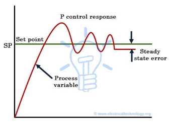
Term P is proportional to the current value of the error e(t). It produces a correction which is proportional to the value of the error.

image

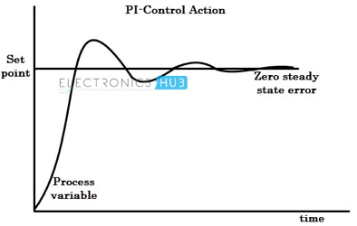
Term I accounts for past values of the error and integrates them over time to produce the I term. This ensures that the sum of errors is zero by producing a counter effect to bring it to steady state.

image (1)

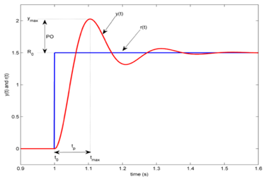
Term D is a best estimate of the future trend of the error, based on its current rate of change and creates a dampening effect.

image (2)

The components we used are: Wood(for the base plate), Web Camera which was attached to the arm of the stand directly over the plate,2  Servo Motors with attached Push Rods, Universal Joint(and extension rod)- on which the plate rests, Acrylic Sheet (plate), Arduino UNO

The complete code is available in the attached link:

https://github.com/abhishekkhurana12345/Ball-Balancing

unnamed

This project was done by the PHoEnix Tech Team.

Keshav Sharan 20171529

Jay Karhade  20180852

Abhishek Khurana  20180621

Arpit Anwani 20180277

Mohit  20180518

Rohan  20180590

Ishika Bhattacharya 20180421

Om Kulkarni  20180518

Voice controlled car

Initiated by :- Yug Ajmera  (2017 Batch)

Hardware Used –

  • Arduino Uno
  • Bread Board
  • Motors x 2
  • Wheels x 2
  • Chassis ( of appropriate size )
  • Voltage Regulator LM 7805
  • Motor Driver L293D
  • 12V Batter ( Power source)
  • Jumper Wires
  • Bluetooth Module HC-05

About Bluetooth Module HC-05

In our world of embedded electronics hackery, Bluetooth serves as an excellent protocol for wirelessly transmitting relatively small amounts of data over a short range (<100m). It’s perfectly suited as a wireless replacement for serial communication interfaces.

HC‐05 module is an easy to use Bluetooth SPP (Serial Port Protocol) module, designed for transparent wireless serial connection setup. The module has two modes of operation, Command Mode where we can send AT commands to it and Data Mode where it transmits and receives data to another Bluetooth module.

Image result for hc 05 bluetooth module

About Voltage Regulator LM 7805

Voltage sources in a circuit may have fluctuations resulting in not providing fixed voltage outputs. A voltage regulator IC maintains the output voltage at a constant value. 7805 IC, a member of 78xx series of fixed linear voltage regulators used to maintain such fluctuations, is a popular voltage regulator integrated circuit (IC).

Image result for lm7808

About Motor Driver L293D

L293D is a typical Motor driver or Motor Driver IC which allows DC motor to drive on either direction. L293D is a 16-pin IC which can control a set of two DC motors simultaneously in any direction. It works on the concept of H-bridge. H-bridge is a circuit which allows the voltage to be flown in either direction.

l293d_motor_driver_ic-800x800.jpg

Software Used

Arduino IDE

Working

We connect the Bluetooth module with the mobile app. Once done, the commands which we give through the mobile get sent to the Arduino via the module. We accept character by character from the serial buffer sent by the app and combine them to form a string.

We then compare it to the command. If it matches the command is carried out. For example, the string we receive is “right” ,the bot turns right.

The video and code for the same are available at:

 http://yainnoware.blogspot.in/p/voice-controlled-car.html

Contact : Yug Ajmera – 9879504650

Secret clap door lock

Initiated by :- Yug Ajmera  (2017 Batch)

Hardware Used :

  • Arduino Uno
  •  Bread Board
  •  LED ( any color)
  •  Resistor ( 10K )
  •  Jumper wire (for conncetions )
  •  Sound sensor module 

Sound sensor module :-

The sound sensor module provides an easy way to detect sound and is generally
used for detecting sound intensity. This module can be used for security, switch, and
monitoring applications. Its accuracy can be easily adjusted for the convenience of
usage.
It uses a microphone which supplies the input to an amplifier, peak detector and
buffer. When the sensor detects a sound, it processes an output signal voltage which is
sent to a microcontroller then performs necessary processing.

Software : Arduino IDE

Working :

Here we are glowing an LED instead of opening a lock for simplicity. You can use a servo motor to open a lock. If a particular pattern of claps is detected , only then the lock will open . For this we are using a sound sensor module. In normal state , the sensor gives HIGH . As soon as a clap is detected , it gives LOW .

Access the code and have a look at the video at  http://yainnoware.blogspot.in/p/secret-clap-door-lock.html

Contact : Yug Ajmera – 9879504650


EasyMouse

AIM:-

Carpal Tunnel syndrome is a common problem with people who are involved in desk-work, working with a traditionally designed mouse, or a pointing device to be more specific. EasyMouse aims to make a pointing device optimised for gaming, based solely on gestures. As a result, Carpal Tunnel Syndrome is avoided in the long run.

INITIATED BY :- AKHIL R BARANWAL (2016 BATCH)

HARDWARE NEEDED :-

ARDUINO NANO

ADXL345

MPU-6050

nRF24L01(for the wireless communication)

ADXL345  is a small, thin, ultralow power, 3-axis accelerometer with high resolution (13-bit) measurement at up to ±16 g.  The ADXL345 is well suited for mobile device applications. It measures the static acceleration of gravity in tilt-sensing applications, as well as dynamic acceleration resulting from motion or shock. Its high resolution  (3.9mg/LSB) enables measurement of inclination changes less than 1.0°.
nRF24L01 is a single chip radio transceiver for the world wide 2.4 – 2.5 GHz ISM
band. The transceiver consists of a fully integrated frequency synthesizer, a power
amplifier, a crystal oscillator, a demodulator, modulator and Enhanced ShockBurst™
protocol engine. Output power, frequency channels, and protocol setup are easily
programmable through a SPI interface. Current consumption is very low.

HOW IT WORKS:-

The ‘driver’  which is written in Python, receives instruction packets from the Arduino and uses pyautogui to perform GUI operations. Since this is a custom mouse, a gesture can be programmed to trigger, for example, 5 mouse-clicks in 250 milliseconds.
Similarly, another gesture can be programmed to trigger a series of perfectly timed combination of keystrokes and mouse-clicks, which are useful in hitting combos in games like Mortal Kombat.General pointing and cursor movement will also have greater precision and sensitivity, all of which can be customised according to personal preference.

All files related to this project are here.

STATUS:- In Progress

Contact:- f20160372@hyderabad.bits-pilani.ac.in

The BIPED/Humanoid project prototype-3

Aim: – To Explore, Study and Solve Various Challenges encountered in imitating human motion in the third prototype, Team Dextroid is planning on improving the previous design and adding a Torso and Arms.

Initiated By:-Suyash Yeotikar(2012), Harshit Agarwal(2014) and Parakh M Gupta(2014).

Team Members:- 

  • Harshit Agarwal (2014)
  • Parakh M Gupta (2014)
  • Suraj Partani (2014)
  • Eda Amos William (2014)
  • Siddharth Chaturvedi (2014)
  • Rohan Dvivedi (2014)
  • Suyash Yeotikar(2012)
  • Murtaza Bohra(2015)
  • Mriganka Saikia(2015)
  • Sarthak Rajvanshi(2015)
  • Kumar Prasun(2015)
  • Somjit Banerjee(2015)


Details:-

Read about Prototype-1 here.

Prototype-3.

After securing a funding of Rs 75000, the team has successfully shifted to a new sturdier mechanical design with low vibrations and walking is also improved. 3D model of prototype-3 made by mechanical team is ready in addition to the previous design the Humanoid now have a torso and arms with 5 degrees of freedom, Acrylic is used for feet paltes and Torso for good strength and light weight ,Arms are custom made and will be 3D printed  . Work on open CV i.e location of points on the ground and path planning is under progress. A server is created on the laptop using the concept of sockets written in python language and the raspberry pi 2 runs the client code.The server sends the servo number(all the servos in the bot are numbered) and the corresponding angle by which it has to rotate from the laptop to the raspberry pi.Using i2c mode of communication between arduino and raspberry pi 2 these values are passed on to the arduino nano.The arduino nano then equipped with the information makes the appropriate servo turn by the required angle.

Current Status of the Project: – Stage-1 & 2 are completed and stage -3 is underway.

Stage 1 & 2 combined video can be found here.

Contacts:-

  1. Harshit Agarwal (2014) –  99122-49068.
  2. Parakh M Gupta (2014) –  77299-92611.
  3. Suraj Partani (2014) –  90105-26919.
  4. Eda Amos William (2014) –  84648-29792.
  5. Siddharth Chaturvedi (2014) –  95429-82077.
  6. Rohan Dvivedi (2014) – 96036-65731

Photos:-   

Ball Picker Robot(BotShot Competition)

Aim:- To build a manually controlled Robot which can pick and drop (at desired location) Table Tennis balls.

Initiated by:- Murtaza Bohra(2015 batch), Prerit Agarwal(2015 batch) & Ebin Philip(2014 batch).

Hardware Used:-
1 – Arduino Nano.

1 – breadboard.

1 – 12V battery supply.

1 – 4-wheel chassis.

1- Buck Convertor

2 – 100 rpm motors and wheels.

1 – castor wheel

1-HC-05 bluetooth module.

1-Micro servo

1-MG995(Metal gear servo)

1-L298 Motor Driver IC

Mechanix Kit.

Software used: – Arduino IDE (you have to install CH-340 driver for  arduino nano) & control Joy stick app (available on play store) for Bluetooth Module.

Working: – The working of the bot is simple it picks up the ball and place/drop the ball at desired location. Full mechanical design of the Bot is made using Mechanix Spares.

To lift the arm Four-Bar mechanism is used and bot is controlled via bluetooth.

Video:- You can find the video here.

Contacts: –

  1. Murtaza Bohra – 91332-34453
  2. Prerit Agarwal – 76618-36607
  3. Ebin philip – 85475-26151

Photos:-

Motion detecting glove

Aim:- To successfully identify the position of a glove from its mean position and detect a throwing action.

Initiated by:- Yohan MR(2015 batch).

Hardware:-

MPU6050.
Arduino uno.
breadboard.
jumper cable wires.

Details:-

The main aim of this project is to understand i2c communication and using the mpu6050 sensor.

Working:-

From the sensor we get the Yaw, Pitch, Roll values which enables us to tell the orientation  of the sensor in space as well as the distance travelled with respect to its initial position.

Setting the base value of yaw pitch roll as the intial position we can compare it the current feed to see how its moved in the xy- plane.

Once we know how far its travelled from the origin the next part is to see if a throwing action is made in the direction of the target. For this like before we compare values In the xz plane and also the rate of change of these  values to see if the hand is moving fast enough.

This is the basic working of the project.

Video:-Video to the project can be found here.

contact:- Yohan MR-9640553127

Ball-balancing Bot(1- dimensional)

Aim:- To balance the ball automatically at the center of plate using PID controller and Machine Learning(supervised learning).

Initiated by:- Abhinav Kumar(2015 batch),Yohan Mmr(2015 batch).

Hardware used:-

2-Breadboards.

2-Ultrasonic sensors HC SR04.

1 – 9v battery power supply.

Jumper wires.

1-Servo motor.
wood-to make the frame,platform and support.


Details:-

The main aim of this project was to apply machine learning(Supervised Learning: Learning with the help of the given examples), to let the bot learn to balance the ball in one dimension(further it will be extended to 2 dimension).

First we measure the distance (position) of the ball using ultrasound sensor. We then calculate the deviation of the ball from its mean position (center). For training we use joystick to train the model how much it should move the servo (which is used to rotate the plate) which is proportional to angle of deviation from mean.

Distance Measurement:

For measuring the distance  or position of the ball on the plate we have used Ultrasound Sensor to determine the deviation of ball from the mean position (center) of plate. We have used two ultrasound sensor (second one would have been redundant in ideal cases as length of plate is known),but due to noisy measurement we had use two.

Joystick:

We have used joystick as an input to train the Machine learning model to predict the response. While training we displace the ball and give input to the computer as in the form rotating the joystick, which should be proportional to the displacement from deviation from the mean position. Its basically like playing ATARI games but in real. There our expert human response according to visual input is given to the computer and the target value for a particular deviation.

After training phase the “learned” model with its parameter was given to the Arduino which then ran and tried to balance the ball automatically. The Arduino measured the distance(position of the ball) the calculated how much it should jerk, using Servo in the right direction to bring the ball to its correct position using the model learned from us.

Video:- Video to the project can be found here .

Current status:- Completed.

Contact:-

Abhinav Kumar – 9705932045.

Yohan Mmr- 9640553127.


Hand Gesture Controlled Robot(IEEE Team)

Aim:- To build and experiment with a hand gesture controlled robot.
Initiated by:- IEEE BITS Pilani Hyderabad Tech Team

Team members :-

Ajay Surya (2014)                   Tech. Team Lead

Himanshu Gupta (2015)         Tech team member

Lohith Artham (2015)              Tech team member

Vibhor Govil (2015)                Tech team member


Hardware Used:-
2 – Arduino Uno.
2 – breadboard.
1 – 9V battery supply for motors
1 – 9V battery supply for Arduino
1 – chassis.

1- Accelerometer

2 – 100 rpm motors.

2 – 100 rpm motors

1 – castor wheel Power bank

1-RF Pair

1-L298 Motor Driver IC


Software used: –  Arduino IDE.

Working: –  The hand which is controlling the bot basically has 3 important components which are an Arduino chip, a radio transmitter (sender) and an accelerometer. As we tilt or move our hand in particular angle, the accelerometer detects motion along the 3 axis and gives the inclination to Arduino attached on the glove which in turn sends it to the receiver on the bot and moves the bot accordingly.

Current status: – Completed.

Video:- The video of the project in action can be found here.

Contacts: –

  1. Ajay Surya – 97032-28934
  2. Himanshu Gupta – 97059-34650
  3. Lohith Artham – 95057-98180
  4. Vibhor Gohil – 94287-67600

Photos:-


Obtascle Avoidance Vehicle 2.0


Aim:- The aim of this robot is to avoid all the obstacles in its path and to move on the path that is less crowded.

Initiated by:- Somjit Banerjee(2015 batch).

Hardware Used:-
1 – Arduino Uno.

1 – breadboard.

1-9V battery supply for Arduino.

1 – 12V supply for motors.

1 – chasis.

2 – 100 rpm motors.

1 – regular sized castor wheel.

1 – ulrasound sensor.

1 – servo motor.

Software used:-  Arduino IDE.

Working:- This uses the ultrasound sensor to calculate the distance of the object in front of it and it is programmed in such a way that if the object distance is less than 30 cm the bot stops moving forward. The servo motor then makes the ultrasoundsensor turn 90 degrees right and records the distance and then 90 degrees left and records the object distance.Depending on which of the object distances (left or right) is less it takes a turn towrads that direction and continues to move forward until the initial condition is met.

Video:-  Video to the project can be found here.

Current status:- Completed.

Contact:- Somjit Banerjee-9833091869.